Electronics
***This document will show how to setup the electronics of the Lemon robots. Each section will go over both how and why each part is used. Some of the parts or wiring that are given as examples in this guide may not be exact to yours, like how you may have chose a different brand of voltage regulator than the one used in the guide or the ports you may have used for your wiring. As long the components are listed with a * those parts of the circuits are interchangeable.***
Introduction To The Raspberry Pi Pico (RP2040)!
When it comes to everything related to electronics and the operation of the robots the brains of the operation will be the raspberry pi pico microcontroller, also known as the rp2040. This microcontroller features a robust set of control features for many different protocols such as I2C and PWM. First let’s familiarize ourselves with the layout of the pico.
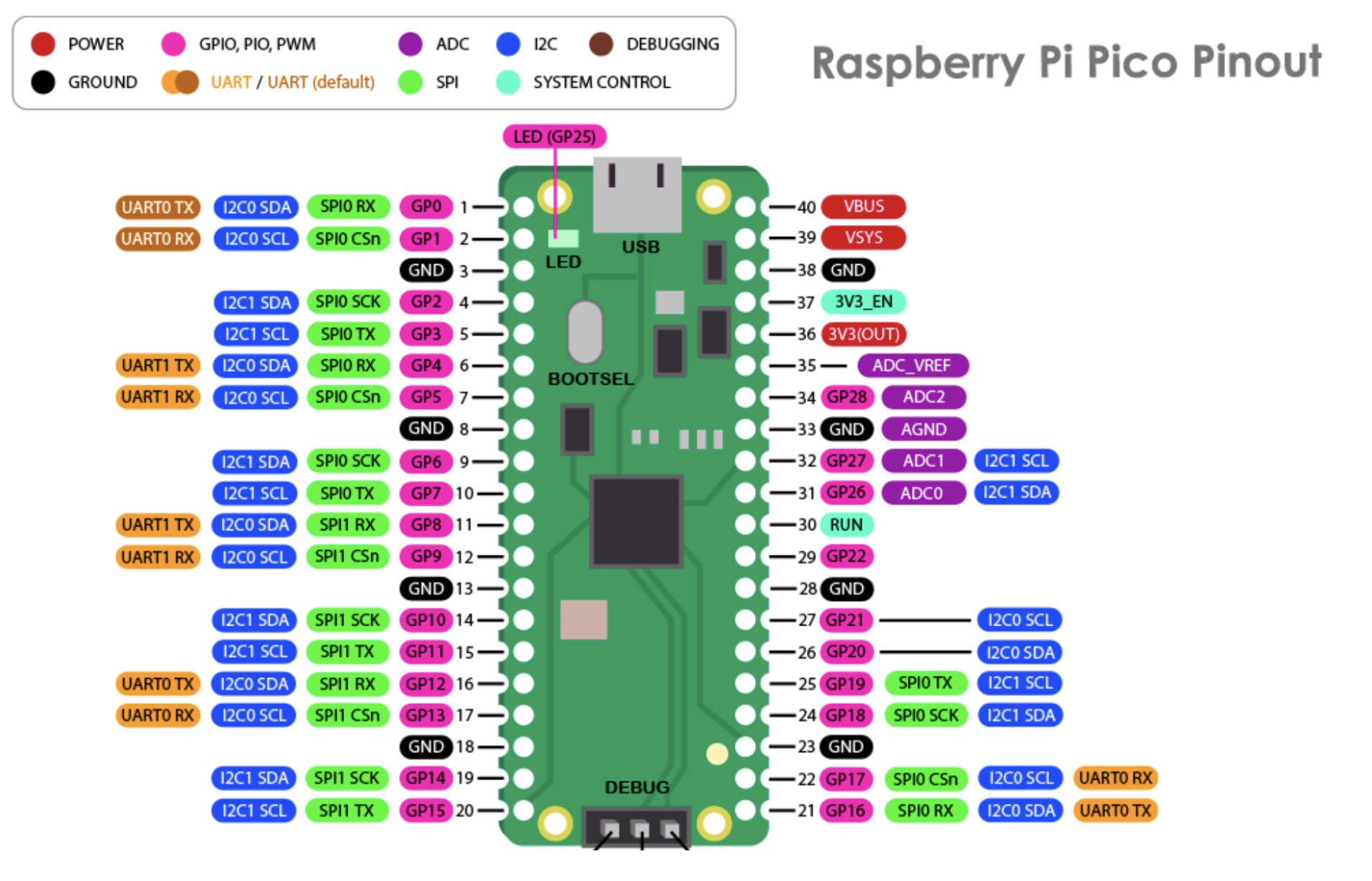
Looking at the above picture and at your own pico the most noticeable and familiar part of the microcontroller should be the usb port at the top. We will be using this port to connect to our microcontroller and send over the data we need such as code. If the pico’s connection to the computer is severed at any point the pico will lose it’s power source, thus all working process will cease immediately, so the connection must remain stable at all times. Alongside the usb port is the bootsel button; this button can be used to access the pico’s memory through our computer, which gives us permission to send data. After installing curcuitpython holding bootsel will not be necessary everytime we boot the pico. Lastly among the parts we will use are the GPIO (General Purpose Input Output) pins to the side of the pico. These pins have many uses, as can be seen from the diagram above, but the most important types for this set of kits are GND, 3V3(OUT), and I2C.
GND: We will use these pins to ground any additional hardware that we might use with the raspberry pi pico, such as servos.
3V3(OUT): For the purposes of all the electronics we will be using it is paramount that you remember to use this port instead of VBUS, because while the 3V3(OUT) pin provides a current of 3.3 volts, the VBUS will send a current of 5 volts which puts our components at risk. Therefore for any power coming out of the pico we will be using the 3V3(OUT) pin, aka pin number 36.
I2C: I2C, usually written as I2C, stands for I2C stands for Inter-Integrated Circuit. It is a bus interface connection protocol incorporated into devices for serial communication. We will be using I2C to communicate with our PWM driver, the PCA9685, as we add more servos to control. I2C needs 2 lines to communicate with devices: SDA to transfer data, and SCL to carry the clock signal. These channels are bi-directional so they allow two-way communication between devices. Thanks to I2C we have a fast method, that has a low cost on available memory space, for exchanging data between our microcontroller and external devices.
All of these pins are numbered both physically and in the form of their GPIO address representation, like GP25, GP0, etc. In this documentation we will be using their physical placements numbers while attaching electronics and refer to their addresses while programming. This concludes all the necessary pre-requisite information concerning the raspberry pi pico.
Downloading Curcuitpython And Library Dependencies
Because we are using a microcontroller, our choice of programming language is very limited due to the similarly limited nature of the ram of microcontrollers. Nevertheless it still remains one of the most important choices as the type of language we choose determines the accessibility of the kit. Therefore we decided that curcuitpython would be the best choice for our kits, since it provides the ease of use and readability of python in an optimized and streamlined package without the different syntax of micropython, and libraries that are directly compatible with the adafruit PWM driver (PCA9685).
1) To install curcuitpython on to the pico first you need to go to this link and download the latest uf2 file.
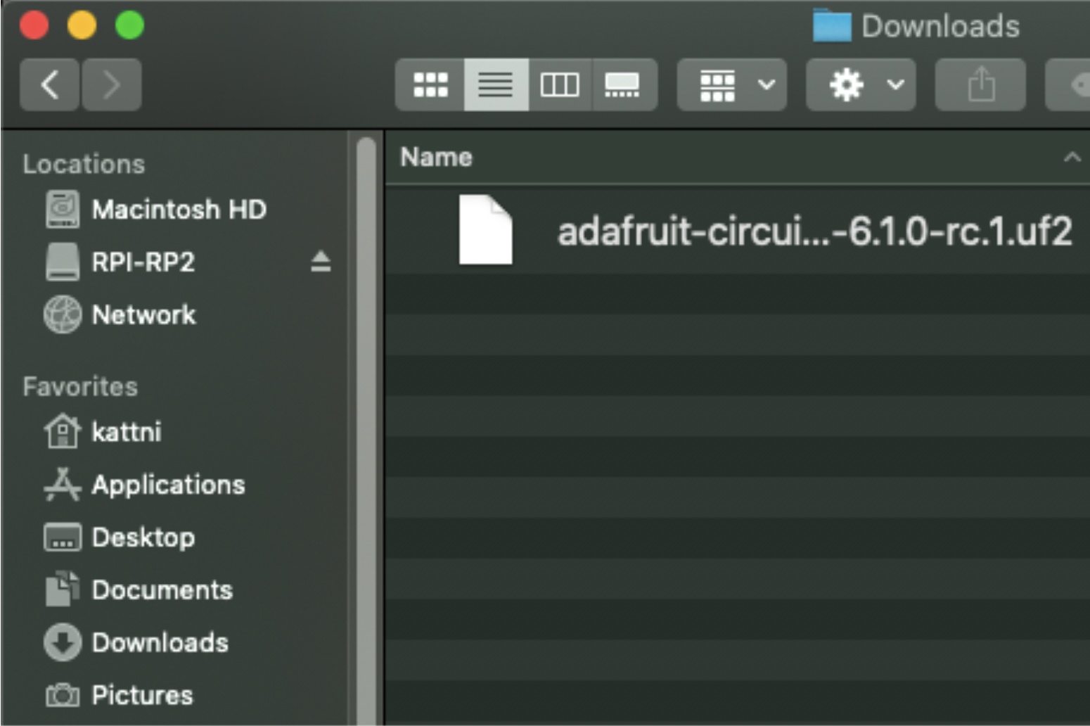
2) Start with your Pico unplugged from USB. Hold down the BOOTSEL button, and while continuing to hold it (don't let go!), plug the Pico into USB. Continue to hold the BOOTSEL button until the RPI-RP2 drive appears!
3) You will see a new disk drive appear called RPI-RP2. Drag the adafruit_circuitpython_etc.uf2 file to RPI-RP2. The RPI-RP2 drive will disappear and a new disk drive called CIRCUITPY will appear.


Next we need an editor to code our pico. To code our pico through curcuitpython we will be using the Mu editor, since this editor supports the use of curcuitpyhon out of the box. To install mu you can go this link and select the version appropriate to your operating system.

The first time you start Mu, you will be prompted to select your 'mode' - you can always change your mind later. For now please select CircuitPython! The current mode is displayed in the lower right corner of the window, next to the "gear" icon. If the mode says "Microbit" or something else, click the Mode button in the upper left, and then choose "CircuitPython" in the dialog box that appears.

Mu attempts to auto-detect your board on startup, so if you do not have a CircuitPython board plugged in with a CIRCUITPY drive available, Mu will inform you where it will store any code you save until you plug in a board. To avoid this warning, plug in a board and ensure that the CIRCUITPY drive is mounted before starting Mu.
Finally we will need to install some of the adafruit libraries so that we can use our electronic components to their full extent. You can download these through this link. Afterwards you will need to copy them to the curcuitpython drives lib folder.