Model A or Model B?
Two versions of the same ship. The lesson, the diffuser, the battery holder, the LEDs and the stickers are shared. Only the body and the place of the electronics differ. The lab team builds both and decides with the same tests.
Compare them in the 3D explorer (use the Model A / Model B buttons)
What is different
| Model A: under the plate | Model B: LEDs outside | |
|---|---|---|
| Body | 3 radial panels (open, Y shaped) | 3 panels in a triangle (closed) |
| LEDs | Under the plate, shining down into the diffuser | On one "power panel", shining outward |
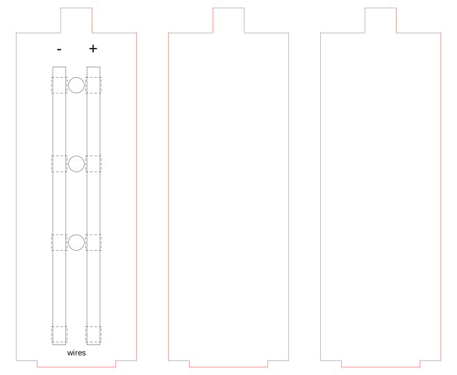
| Copper rails | 2 straight rails, 54 mm, under the plate | 2 straight vertical rails, 106 mm, on the power panel |
| Wires | None | 2 short wires from the holder, up through the plate, to the rail bottoms |
| Battery holder | Under the plate | Under the plate (same) |
| Panels | 3 identical | 2 plain + 1 power panel |
| Sticker area per panel | small (about 13 to 46 mm wide) | large (46 x 120 mm) |
| Nose cone | 46 mm, glows a little (estimate) | 66 mm, decoration only |
| Diffuser | Glows | Does not glow (LEDs are outside) |
| What the student sees | The circuit while the plate is upside down, then it is hidden | The LEDs and the copper tape all the time |
| Electrical joints | LED legs on one flat plate | LED legs (6) and wire ends (2) on a vertical panel |
Why B is worth testing
- It matches the original brief: LEDs facing outward, straight rails, closed body with room for stickers.
- The student can see the circuit working, and can troubleshoot by looking.
Why B can fail (unverified)
- Wires and joints. Eight joints on a vertical panel handled by children. Wires can pull off the rails.
- LED hold. The LED stands on its folded legs under two copper patches. It may tip or lift.
- Corner slits. The panels meet at 60 degrees with a gap of a few millimetres at each corner.
- Panels wobble until the nose cone locks the top tabs.
- Bigger nose cone (66 mm) uses more plastic and print time.
- Fewer parts under the plate, more on the outside, so more things can be bumped.
Parts needed for B (differences only)
| Part | Note |
|---|---|
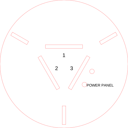
| Base plate B | v1b_base_plate_laser.svg |
| Panel set: 1 power panel + 2 plain | v1b_panels_set_laser.svg (cut one set per ship) |
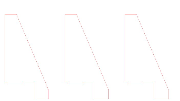
| Wings (3) | v1b_wing_laser.svg |
| Nose cone B | 3d/v1b_nose_cone.scad, v1b_nose_cone.stl |
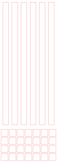
| Copper band for the GS-24 (3 kits per band) | v1b_copper_rails_gs24_cut.svg |
| 2 thin flexible wires, about 12 cm, red and black, 5 mm stripped ends | about 24 to 26 AWG, to be confirmed on the bench |
| Diffuser | The same part as Model A |
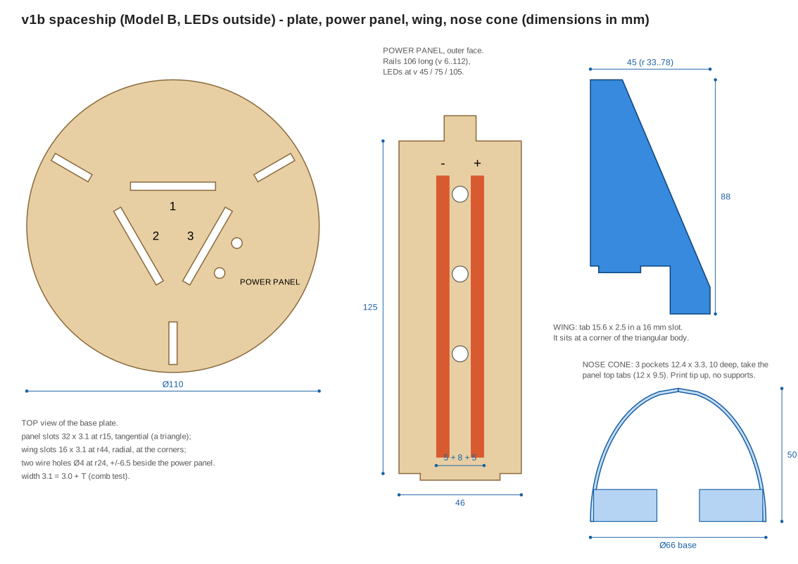
Build order for B
- Stickers on the flat panels and wings.
- Stick the two rails on the power panel (follow the engraved lines).
- Place the three LEDs, long leg on the + rail, and press a copper patch over every leg.
- Battery holder under the plate. Push the two wires up through the two holes.
- Stand the power panel in its slot. Press each wire end onto the bottom of its rail with a patch.
- Switch ON and test. Not lit? Battery, switch, LED direction, tape contact, LED legs.
- Stand the two plain panels in the slots, put the nose cone on the top tabs.
- Wings into the short slots at the corners.
How we decide
Both models must first pass the electronics gate: 10 builds, 10 working ships. A model that fails the gate is out, whatever its score.
Then score each model from 1 (bad) to 5 (very good) on the lab's priorities. The weight is the priority rank.
| Priority | Weight | How to measure |
|---|---|---|
| 1. Reliability | 8 | Gate result, and joints still working after a gentle shake and a gentle tug on the wires |
| 2. A child can build it alone | 7 | Share of volunteers who finish without help |
| 3. Fits in 60 minutes | 6 | Build time (adult 15 to 20 min, child 35 to 45 min) |
| 4. Easy to troubleshoot | 5 | Time for a helper to find a planted fault |
| 5. Scales to 140 ships | 4 | Cut and print time per kit, number of parts, joints per ship |
| 6. FabLab processes are visible | 3 | Does the student see what each machine made? |
| 7. Looks great | 2 | Dark-room look from 3 m |
| 8. Makes children curious about CAD | 1 | Pilot feedback |
Weighted total = sum of (score x weight). Write the scores in the A/B decision issue, and use the CSV templates in projects/welcome-space/tests/.
Tests to run on both models
| Test | What to record |
|---|---|
| Build time with an adult, 5 ships each | Minutes, first-try success |
| Gate: 10 builds | How many light all 3 LEDs |
| Shake and tug | Do all LEDs stay lit? Which joint failed? |
| Stands upright | Wobble before and after the nose cone |
| Dark room, 3 m | Are 3 LEDs visible? Is the nose cone lit (A)? |
| Cell change and switch | Easy to reach? |
| Planted fault | Minutes for a helper to find it |
Assumptions to check for B
| ID | Assumption | Status |
|---|---|---|
| B1 | Wire ends stay on the rails under a copper patch | Assumed |
| B2 | An LED stands on folded legs under two patches without tipping | Assumed |
| B3 | A 2 mm gap at each panel corner looks acceptable (or can be hidden with a sticker) | Assumed |
| B4 | The triangle of panels stands once the nose cone is on | Assumed |
| B5 | A 4 mm wire hole is enough for a thin silicone wire | Assumed |
| B6 | The 66 mm nose cone prints in about the same time as the 46 mm one | Assumed |
Record the decision in the assumptions log and in CHANGELOG.md.